
Fully Insulated Wire
General
About
FIW (Fully Insulated Wire) is an alternative wire to build switching transformers typically using TIW (Triple Insulated Wires). Due to the big choice of overall diameters it allows to produce smaller transformers at lower costs. At the same time FIW has better windability and solderability compared to TIW and still provides all protection classes: basic, supplementary and reinfoced insulation.
FIW is produced in a multiple coating process, which guarantees insulation without any defects.
ELEKTRISOLA FIW is approved as MW85C and according to OBJT2. It has been sold successfully for several years to the automotive industry and for applications which do not require UL approval acc. to UL 60950. As Elektrisola FIW is approved as MW85C it can be used by many Insulation Systems according to UL 1446. The Safety Standard IEC 62368-1 Edition 3 is approved and allows the use of FIW. The old Safety Standard IEC 60950 was withdrawn end of 2020.
The FIW Wire
Elektrisola developed a product based on a modified polyurethane with a life time acc. to IEC 60172 of 20,000 h at 180 °C, short designation P180. It is produced with multiple passes of individual covering of insulation and is in-line tested for high-voltage-continuity to assure the perfect insulation without any insulation defects.
FIW is defined with many Grades specifying different insulation thicknesses. FIW 3 is the smallest defined build, while FIW 9 is the biggest.
Elektrisola Standard FIW Grades ex stock are FIW 4 and FIW 6, as they give a good compromise between good technical performance and affordable costs.
Electrical Insulation System (EIS):
The reinforced FIW can also be used as Filament Wire in the following EIS-Systems.
- DuPont Specialty Products USA, LLC (EIS-No: E57692)
- CELANESE INTERNATIONAL CORP (EIS-No: E69939)
- SUMITOMO BEKELITE CO. LTD. (EIS-No: E209189)
Specifications
FIW is specified in different specifications. Basically there are Standards for enamelled wires, such as IEC and NEMA, but there are also Safety Standards, such as the old IEC 60950, replaced by IEC 62368-1, and UL Safety Standards, such as UL 2353.
In these Safety Standards, FIW is permitted to be used as reinforced insulation.
In addition, some values are also specified in product standards as the Transformer Standard acc. IEC 61558-1.
Product
IEC 60317-56 and 60317-0-7
NEMA MW85c
UL 2353
Test Conditions
IEC 60851
IEC UL 60950 Annex U
IEC 61558-1
IEC 61558-2-16
UL 2353
Advantages of FIW
- choice of different insulation builds (with different insulation thicknesses) allows optimization of products like smaller transformers and gives a cost advantage
- excellent solderability
- superior windability
high temperature class of 180 °C, thermal life time acc. UL 60950 Annex U tested in transformers for temperature class 155 °C/130 °C
proven insulation system acc. UL 1446 of enamelled wires also with UL, used over many years
reinforced insulaton according to UL2353
Example 0.25mm FIW 6, 390°C, 2.4 sec.
Production Process
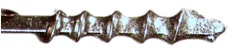
The basic production process is similar to a normal enamelled wire  Production Process, but has many more single wire passes - up to 120 - to generate the finally very thick enamel layer, as shown in below photo, where always 3 alternate layers were coloured to demonstrate the big number of layers.
Multiple layers of a 0.25 FIW 7
In addition, every production line is equipped with an In-Line High Voltage Continuity Tester, which checks the insulation of the wire over the complete length permanently to guarantee that there is no insulation fault.
Packaging
The FIW wire is spooled on standard spools used in Europe and in Asia
Delivery ex Stock
Many FIW wire configurations can be supplied ex stock. In the table Dimensions the grey highlighted diameters and builds are typical stock items.
Technical Data
Standardized Properties of FIW
IEC 60317-56 describes a full Enamelled Wire Specification with mechanical, electrical, thermal and other characteristics like soldering
UL 2353, rather similar to IEC 60950 Annex U, gives mainly electrical properties which mostly are rather short-term tests
The new Safety Standard IEC 62368-1 continues with the same requirements, taken partly from the Transformer Standard IEC 61558-1 for FIW.
Breakdown Voltage
Breakdown Voltage (BDV) values for FIW will vary depending upon which standard is used to calculate these values.
When using the enamelled wire standards for FIW (IEC 60317-0-7 and 60317-56) the BDV is calculated using the minimum insulation increase per size, (min. insulation increase = min. OD including insulation – nominal bare wire dimension).
BDV calculation acc. IEC 60317-0-7
The minimum values can be found in IEC 60317-56
Minimum BDV acc. to IEC 60317-56
The Transfomer Standard IEC 61558-2-16 was finally corrected as the BDV calculation in the old version mistakenly used the minimum insulation increase divided in half, erroneously resulting in approximately half the BDV values as the magnet wire standards.
IEC 61558-1 as a new version of IEC 61558-2-16 has already been released, correcting errors (like the BDV calculation described above) found in the previous version. One major difference: The new version requires the FIW to maintain durability for dielectric strength for one minute at 180 °C with a factor of 0.85 compared to IEC 60317-0-7. Here the dielectric strength is measured by Breakdown Voltage (rms) at room temperature.
Minimum BDV acc. to IEC 61558-1
IEC 62368 follows the BDV values of IEC 61558, but does not specify 180 °C as test temperature as IEC 61558
Calculation of Breakdown Voltage
The minimum breakdown voltage acc. to IEC 60317-0-7 can be calculated with the nominal diameter and the FIW Grade by tool
Dimensions
Dimensions of FIW depend on the Insulation Grade, which describes the amount of insulation on the bare wire
Voltage or necessary FIW Grade by diameter for a given voltage can be calculated by a calculator
Weight / Length
Due to the extraordinary thickness of the insulation of FIW the length of a certain quantity of FIW and the weight of a wire with a certain length deviate remarkably from experiences with normal enamelled copper wire.
The length of 1 kg of FIW 3 - FIW 9 for nominal diameters in the range of 0,071 - 0,710 mm - assuming nominal outer diameters acc. to IEC 60317-56 - can be looked up in the FIW Length Table on the next page in km/kg.
The weight of 1 km of FIW 3 - FIW 9 for the same range of nominal diameters - with nominal outer diameters acc. to IEC 60317-56 as before - can be looked up in the
The weight or length of a specific FIW wire can be checked by a calculator
Approvals
FIW is approved for different classifications:
UL for MW85C, UL File OBMW2.E331840
UL for OBJT2, UL File OBJT2.E316900
VDE Certificate Number 40036030
- UL Insulation Systems acc. UL 1446
- IEC 61558-2-16 for transformers (SMPS) specifies use of FIW and IEC 61558-1
IEC 62368-1 as new Safety Standard, replacing IEC 60950
UL Electrical Insulation Systems: